Monday, November 21, 2016

Inexpensive RFID Door Controller

This is a door controller that goes by a variety of model names and numbers on the internet from Amazon and Ebay.

I'm not an expert with these systems, but have quite a bit of time using them with multiple controllers running in multiple cities in a wide network and they have proven to work very well.  I think we invested around $3000 all the hardware to do about 20 doors (strikes, readers, mag locks etc), Plus another $2500 in wire.  We did all the installs ourselves, there might be other costs if you aren't able to install it.  Around 250 users, thousands and thousands and THOUSANDS of entry/exit processing, have never had a single issue yet in the last 3 years running them.

Hopefully there is information here that will help, feel free to leave comments or questions, I'm glad to help and I hope what I have here is useful to someone trying to implement it.  My documentation is more on the installation and wiring of the system, more than it is the day to day operation.  That is covered fairly well in the manual, but the implementation isn't the greatest.

"Wiegand 26 Bit TCP IP Door Controller"

HSY-02B HSY-04B HSY-01B

https://www.alibaba.com/product-detail/HSY-Manufacturer-TCP-IP-Door-Access_763217699.html

Similar controllers are the 02b and 01b

There is also either a big brother or maybe a cousin to these boards made by Wiengand called the 2004.net
http://www.wiegand.com.cn/english/support.htm


It seems too be a a similar unit, upgraded/different different design perhaps?  I'm not sure but specs and board layout pins seem to be similar.  The import reason for mentioning it is that this site has some additional software that you can try with these apps.
WHAT DOES THIS DO?
So the RFID system, purchased from mostly suppliers in China, is a fairly inexpensive and capable cardkey RFID card system to open doors based on the cards level of access and assignment to both doors and time conditions for those doors.  Once up, you can place your keycard or FOB or other RFID programmed entry device against or near the 'reader' and if your card is authorized, the door will unlock.  Generally speaking, you can leave the cards inside a bag or in your pocket, and simply placing the holder near the reader, and using a radio signal, it can communicate with the FOB and unlock the door if you are authorized.


HOOKING IT UP

Administration Software to the controller(s)

This is actually pretty easy.  These controllers can be standalone, meaning you can buy an RFID controller, and just use the simple GUI on it to control cards and who can get in or out.  If you have 1 controller and maybe less than 25 people, this isn't so bad, since you may only have 4 doors to worry about.  But lets say you have hundreds of people and 8-16-100 doors?  Well you'll want to use the management application that interfaces to these doors.  (its outlined below).  The management application gives far greater control of the doors and the features.  It allows you to manage large number of users access, remote activate/deactivate doors with some mouse clicks, and a large number of other security features that aren't necessarily available.  

The software 'talks' to the RFID boards and uploads/downloads the data.  The management software is not needed to run the doors, its only need to do add/moves/changes to the system.  ALL the doors run 'autonomously', independent from the controller.  So if you shut off the computer running the administration software, the doors don't care, they just keep on doing what they're told to do.  When you make the changes you need to user access, you 'upload' this data with a click of a button to all the controllers, and that data is then sent to the memory of the RFID boards.  Also you can download the data from these boards to the controller computer, merging all the different doors into a single utility to run reports.  Very convenient and easy.  The best part is that the RFID boards are connected to the management software via Ethernet.  Beneficial in larger deployments where you might have a corporate office with doors spread far apart within a building or in different cities.  If there is an established network to those offices, and the management computer can talk to the other networks, you are able to manage those systems.

YES you technically control these boards across the internet, I would highly discourage that practice as the security access to the board itself maybe easily compromised by hackers, we do not know.

RFID Door Controller

There are variations of the same system above that can control more or less doors, this one pictured below has 4 door input/output controls, but the input/output configuration is the same among the various models

First thing.  The board itself needs power,  You'll want a power supply that can deliver 12volts with a 3-5A rating (connects to P2).  This will power the controller and will provide 12volts output to the RFID connections (RD1 - RD4).  The DC amperage requirements will dictate how you are power devices.  If you have controllers that need to be enegergized in their normal state, its going to be higher power usage than systems that only require power to unlock, assuming its a momentary unlock.

This P2 power connection does NOT provide power to the door strike connections DR1 - DR4.  Power for these connections is provided to the "COM" input on each connection from a separate 12 volt power source.  What this means is a relay on the board itself controls the power from the COM input to the NC/NO input.  So you'll notice in the diagram I have 12 volt sources connected to each COM input (common).  TECHNICALLY yes these could all come from the same 12 volt power supply.  Sometimes some users wish to separate the power.

Ive been using these types of power supplies
UHPPOTE AC100-240V to 12V/5A Power Supply Support Backup Battery
Lots of power to run the controller and strikes.  It also has a built in battery charger and will allow the system to continue to function on battery.  Available on Amazon for around $20   They have a lot of functionality in it.
Electric door strikes and magnetic locks can consume a lot of power and should be sourced separately from a different supply than the one powering the board, since its requirements are very.  You don't want to burn out the power supply.

The top and bottom of the board is used for the RFID readers and the exit buttons.

On the right hand side are the door strike connections and mag log controls

Connection Layout Diagram Example
In the diagram above, there is an example of 3 different door types connected.  

Door 1 uses a door strike that is activated with a reader.  This example has a green push button "release" to manually unlock the door for exit.  The strike normal state (no power) is 'locked'.  This means it needs power to unlock.  So it is connected to the "Normally Open" connection on the board.  The "NO" or "NC" doesn't refer to the lock state, it refers to the type of power the door strike needs.  OPEN means the circuit has no power, and only has power for the duration you want to keep the door unlocked.   So on the RFID board, the "NO" connection gets power when a card is successfully used,  a "NC" connection removes the power for the duration you want the door to unlock when a card is used.

Door 2 uses a magnetic lock.  It is connected by a separate 12 volt power supply.  It is using a request to exit button as well, however this button uses a motion sensor to trigger the exit, so it requires an additional power connection to it, which is 12 volt in this example.  The magnetic lock is connected to the "NC" connection.  This provides continuous power to the electro-magnet, and then 'opens' the circuit to cut the power to it to allow the door to open.

Its important to note that there are different magnetic lock types.  The above example, the power to keep the magnetic lock energized and locked is flowing through the controller.  Some magentic locks have independent power to the lock itself, with a separate power feed coming from the RFID to remotely trigger the power on or off in the magnetic lock itself.

Door 3 (currently not connected in the above example, ran out of space on the picture :) )

Door 4 is an example of controlling a latch via separate relay.
WARNING: You need to have some electrical concepts in place to prevent sending power to a system not expecting it.  Implementations are very situation dependent, this example is only a possible solution in a certain set of circumstances.

This example the door latch that is already connected to an existing door system which is priority.  This situation may stem from a shared door where you might have 2 different companies using the same door, each wanting their own system, but need to work with each other, but independently.

This example, the latch is 'normally closed', meaning there is power to the door to keep it locked.  This would be typical of some door strikes, but more commonly a magentic lock.

Since we want to interrupt the power to the door for the duration of our system, the example shows a 'normally closed' relay being inserted into the power connection for the door lock.  We'll use a relay, controlled by our RFID system, to interrupt the power to this strike when our system wants to open it.

The relay is a normally closed relay and allows the power to the strike to flow through it.
The RFID system is controlling the relay through a NO circuit.
When our system wants to unlock the door, it DR4 changes from the normal "NO" state to a NC state, which sends power to the relay.  The relay activates, and changes from a "NC" state to an "NO" state, which cuts power to the lock and sets the door to unlocked.

RFID READER

I've made a few different model of RFID readers work, but really MOST of the ones I've tried all worked the same.

The basic connections on RFID readers are these:
POSITIVE   - RED
NEGATIVE - BLACK
DATA0 -  GREEN (usually)
DATA1 - WHITE (usually)

There are others, but all ones I connected up worked with this configuration right away.

This is an HID ThinLine II reader and it works with the board discussed in this document.


This is an "HID" reader below, which was $20 from China, so probably less quality, but the ones I have work just fine so far.


This RFID reader can support pin/rfid combination access.
These RFID readers work with and without the use of the key pin pads (to go with the cards).
We use these readers on external doors that are public accessible.  This is due to the insecure nature of RFID skimmers.  These require an RFID pass plus a user pin number to work in conjunction to open the door.

Googled: " s touch s key reader pdf "
and found this PDF document with instructions

https://www.i-keys.de/download_free/sTouch-sKey%20standalone.pdf

Door Strikes

The door strike is operated by electronically by the door controller.

This P2 power connection does NOT provide power to the door strike connections DR1 - DR4.  Power for these connections is provided to the "COM" input on each connection from a separate 12 volt power source.

Electric door strikes and magnetic locks can consume a lot of power and should be sourced separately from a different supply than the one powering the board, since its requirements are very.  You don't want to burn out the power supply.

The controller has connections for either mode.  The important thing to understand is that the system doesn't provide any power to these connections.  You must feed power alternately into these feeds.  

In this diagram, you'll notice that there are two power connections from the power supply going to same board.  The top power connection in the picture is the power for the boards electronics.
The second power connection you see is dedicated solely to the strikes.  Some power supplies have multiple outputs, sometimes you can share.  

The method shown allows you to have dedicated power sources for the strikes.  It also reduces the power required running through the electronics on the board itself.

In this example, the positive line goes to the COM connection on the associated door that you are working on.  Then, depending on the operational type of your strike, you connect it to either Normally Open, or Normally Closed.  In the above example, the strike is a normally closed strike, meaning power is always required to keep the door locked.  When an authorized card is used, the power is turned off to the strike for the duration programmed in the controller, and the door stays unlocked for that time period.

Request to exit button
RFID systems allow a door to open usually either the door handle, latch or magnetic lock on the door frame.  In cases of egress, we need to allow this door to open.  In most cases, door handles, for egress, are usually unlocked.  This means you can, regardless of card state, turn the door handle or push the crashbar and open the door to get out.
In some cases, the handle itself on the door isn't enough to override the system when exiting, In the case of a magnetically locked door, you may require to press a button to release the magnetic lock.  Some, as you approach, sense your approach and will automatically release the door.


 so you need to have some sort of mechanism that detects you are trying to exist and will allow you to do so without a card.  The request to exit button contact, when activated, will trigger the system to release that door for a time period.


On my implementations, my request to exit button itself needed power to light up a light on it.  So I doubled up the power draw from the same power connections that the RFID reader used.


Forced Open/ Open Detection
These boards require an additional module to do some additional input output.
Forced/Unauthorized opening or the leaving of a door open can be detected using a door open sensor

First you'll need this board which connects to the expansion port of the door controller


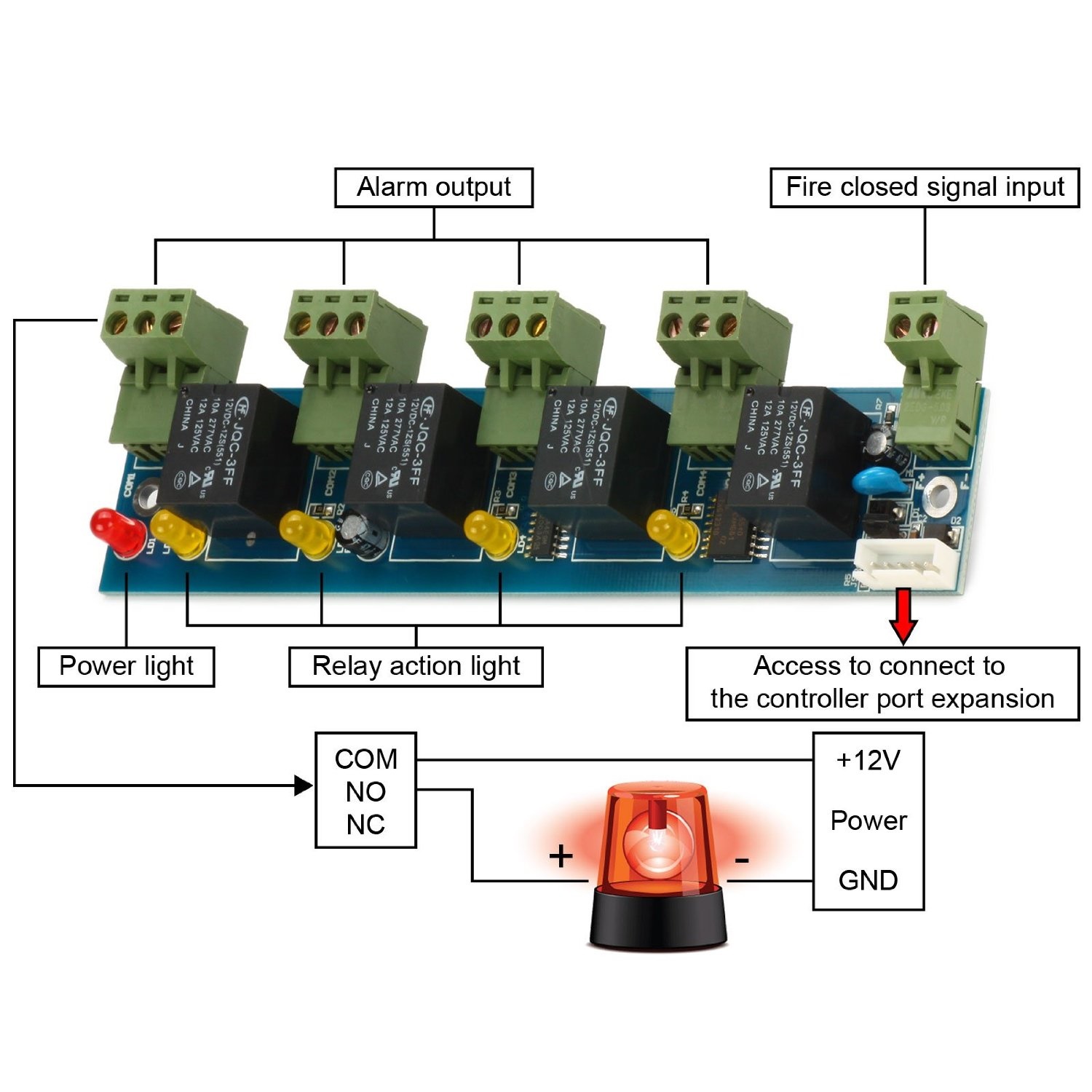
This board can also be connected to a fire alarm panel, allowing the system to unlock all doors upon the activation of a compatible fire alarm system.

In the diagram this shows the "ALARM OUTPUT" connections, however these can serve as inputs alternatively.

So, for example, you connect this module to your alarm panel, then wire a door open sensor to it.


in the software you can program this, that, upon the door being pushed open without a request to exit or a card (IE someone has forced the door open or left it open) the system can detect it and send an alarm or warning.


Software
The software that is used by these systems appears to be the same flavor of software, just used by various different companies.  The link to the Weingand site has a download you can install and try.  I think you need to register it to make it work long term.

WGACCESS Software (WINDOWS ONLY)  That latest version is 8.97 at time of running.
.  I'm running 7.95 on Windows 10 and 2012R2.  7.75 seems to work on windows 10 too.


Here is an alternate link to the 7.95 version of software 

http://www.wiegand.com.cn/soft/soft_all_32/MJ_all_en.rar

http://www.wiegand.com.cn/english/support.htm

(Access Control + Time & Attendances + Patrol )

Default user and passwordUser: abc
Password: 123
Extended Function password: 5678
Registration code is 2004

There is a OPENSOURCE inituitive with these controllers, I haven't done much with it yet, but here is a link to it https://github.com/carbonsphere/UHPPOTE


ACCESSING THE DEVICE
There is a built in web GUI in these controllers once they have an IP
http://IP of the device

I've run into challenges sometimes obtaining the default IP of these units. What I find works best is to attach the RFID board to the exact same network as the PC controller software is.  This isn't usually a problem when you are on a flat small network, but if you are running this in a bigger network that has different vlans, this will help configure it.  I have, in the past had to hook up wireshark on a computer to the controller to determine the IP.  There are lots of online tutorials how to do that, its an alternative path if you have trouble with the IP.

Have it search and detect it.  Then when you configure that board, set it to the IP of the network you want it to be part of (if different than your PC controller software).

Try the following user/password combination
user (aka "System Manager" default) is " abc "
password (default) " 654321 "

Here's a link to a manual to a version of this application.  There seem to be a few floating on the net.HERE

There's a MS Access database in the system, the password for it is 168168 " if you want to look at the tables.

FAQ

QUESTION:
Where can I download the controller software?

WGACCESS Software downloaded at http://www.wiegand.com.cn/english/support.htm

QUESTION:
Do I need the door administration software on my computer running all the time for the system work?

No.  The software is for administration purposes only.  You assign cards and permissions in the software, the you upload the data to the controllers.  Once that data is uploaded, the controllers run autonomously.

QUESTION:
Does the software gather logs automatically?

No.  You must click on the controller and do a download to gather the exit/entry log history

3> QUESTION:
I've hooked up ethernet to the door controller board, how do I connect?

The board DEFAULTS to DHCP. 

  • If you have access to the router that hands out DHCP, you can look in the routers DHCP table to see the IP assigned to it.
  • If you know the IP, and the controller is on a different, but local/route able LAN segment, you can manually enter the IP address in.


  • You can also use the administration software to look for the controller board, however the computer running that software has to be on the same network.


  • What is NO and NC?

    This refers to the type of electric circuit that controls the door and should not be mistaken to be a reference to the type of lock you are using with it.  NO and NC are used to describe the connections (switch or on this RFID controller, relays) and manual switches like emergency stop buttons.

    NO stands for "normally open"  (connections are normally open and close when a switch is used).  Normally Open (NO) stops the flow of electricity until its commanded to 'close ' and start the electricity passing through the circuit

    NC stands for "normally closed" (connections are normally closed and open when a switch is used).  Normally Closed (NC) is a circuit which allows the flow of electricity until its commanded to 'open' and stop the electricity from passing. 

    Normally Lock and Normally Unlock

    There are various types of lock mechanisms, and they generally come in two types of default behaviors when there is no power, or its normal mode, either locked or unlocked.  There are various reasons why you would want this, but its normally decided on the state of the door in its majority of use and/or the state of the door when there is a complete power fail of the system.

    The lock type, in conjunction with their connection to the board dictate their behavior when a card is presented for entry.  And this would be how you want the door to be controlled

    A lock, whose natural un-powered state is locked, would usually be connected to a "normally open" circuit on the board.  When the door is to be unlocked, the controller changes the circuit to "closed" sending power to unlock it the door.

    How many doors can the software control

    100 doors using 25 controllers  (4 doors / controller)

    What type of readers are compatible

    The RFID receiver needs to output a 26 bit
    Wiengand signal. 

    Can I use motion sensors to unlock the door?

    Yes

    Is it possible to open 4 doors with just one keypad but 4 different pin-codes? 

    Yes.  However you can't do it through software.  You would need to wire up the door latches to a relay(s), which would trigger the unlock of the doors.  You would want to be careful of power consumption that the relays use, and the power that is delivered.

    Factory Reset

    I haven't tried this yet, i've put this as a place holder to confirm, but apparently if you connect "SDA" and "GND" and power on the board you should be able to reset it back to factory.


    Monday, October 24, 2016

    Setting up rocketchat on a UBUNTU 16.04 server

    Steps to install on UBUNTU 16.04

    1.     Perform the basic install of Unbutu 16.04 server.
    Using the default drive sizing settings etc are probably fine, especially if you are testing this.

             Set an appropriate username (ex.  Administrator)
             Set the appropriate country
             Set the appropriate timezone
             Set Hostname (ex Rocketchat)

    2.     When installation is completed, server will reboot.

    3.     Log into the server and reboot the box again (Weird Ubuntu thing I’ve encountered in the past)
    Reboot [enter]

    4.     Box restarts, log in and do the following:

    5.     sudo apt-get update
    6.     sudo apt-get dist-upgrade
    (this will take 30 minutes probably)

    7.     sudo snap install rocketchat-server
    8.    reboot

    9.     If you want to hardcode an IP,  eetup IP address by editing the file:  /etc/network/interfaces/
    iface eth0 inet static
    address x.x.x.x
    netmask x.x.x.x
    gateway x.x.x.x

    10.  Save your changes
    11.  Reboot

    By default RocketChat uses port 3000 so, if you want to forward standard :80 port, you can do it with this in UBUNTU with this following commands

    sudo iptables -t nat -I OUTPUT -p tcp -d 127.0.0.1 --dport 80 -j REDIRECT --to-ports 3000
    sudo iptables -t nat -I PREROUTING -p tcp --dport 80 -j REDIRECT --to-ports 3000

    Done!  You should now be, by default, http://IPofYourServer:3000 and be prompted by a rocketchat webpage.
    Register as a new user, this user will automatically become the Administrator user.
    You can go in an resign this permission to other users, so its not permanent.

    Should you wish to update it.  These commands will help:

    "snap find rocketchat-server" will pull the SNAP repository for the latest version.

    "sudo snap refresh rocketchat-server" will update your version to the latest.  Takes a minute or so usually to download, the upgrade is under a minute and users probably will just see some "reconnecting" indications if they are logged in, but usually only takes 10-20 seconds for the service to restart.  Everyone will automatically log back in.

    If running the above sudo command gives you an error similar to the following:
    bla bla bla assumes unsupported features: snapd2.23 

    Try the following command:

    sudo apt update sudo apt install snapd

    The re-run the snap find/snap refresh commands again. You should be good to go.

    Friday, October 21, 2016

    Aligning two sets of data in excel with each other

    Here is how to align two sets of data in excel each set containing multiple rows, but only one common element between the two to use as a 'key'.

    In this example the BLUE and RED need to be aligned, the common element being the 4 digit number.

    Example 1

    With the code further below, the data will look something like this when merged, the red data now aligned with the blue data.


    The data circled above in RED, ( C,D & E ) is now aligned with column A & B in example 2, with all the rows data maintaining their relevant position as well.

    Here's some Excel magic.

    1. First make sure the common data of the two sheets are in the proper columns.  In the BLUE data, which contains the majority of the values, i put the 4 digit number on the right.
      The RED data, which is the lesser data for this example, I put on the LEFT
    2. First selected the the data that you want to align.  (the stuff in RED in my example) and move it to a new tab in the Excel document.

    3. In the new tab you created, make sure the data is selected
    4. In the name box (circled in red below) type in "MyData" in that box.  This gives that selected data a name now.


    Now go back to the original tab that contains the data circled in Blue.
    Were now going to have Excel look at 4 digit in column B (circled in BLUE) and pull data from "MyData" and merge it.

    So, click on an empty column.  I've clicked on column "C" in my example.  Since I have columns to match, I'm going to do the code in 3 different columns

    Assuming that in the blue data, the data is in the second column we would use the following code.
    If it were in the first column, you would use $a1 and if it was in the 3rd you would use $a3
    In Cell C1 put in:
    =vlookup($b1,MyData,1,false)

    Cell D1
    =vlookup($b1,MyData,2,false)

    Cell E1
    vlookup($b1,MyData,3,false)

    Like this:


    Depending on the matches, you may see data appear or see #N/A, which indicates no match.


    Selected the 3 boxes, then auto filled the boxes below with the formula.

    All the data is aligned now.  The boxes that have no matches show "#N/A" in excel.

    Monday, October 3, 2016

    Tether an iPhone to router for Internet access

    Scenario:
    The ISP providing internet to your office/home network (wired and wireless) is unavailable and you need internet to work again.  The method described here will allow you to have multiple connections through your iPhone's data plan using your existing SOHO router.

    To use your iPhone with your router, you will need to utilize a computer that will host the connection between your iPhone and your router.  You can still use this machine for internet access, however it will have limited access to your LAN resources since it is 'outside' the network.


    (Mobile Network Data) <-> iPhone <-> Host Computer <-> Router <-> (wired/wireless LAN)
    1. On the host computer, (tested on windows 7 and 10), plug your iPhone into it with the USB cable.
    2. Enable Personal Hotspot
    3. When prompted with this message, select USB ONLY
    4. After 30 secs or so, windows SHOULD recognize this as a device in your computer network settings.
    5. Now select the "Apple Mobile Device Ethernet", hold down the CTRL key and click on the Local Area Connection that coincides with the Ethernet port of your host computer.

    6. Right click on this and then select BRIDGE CONNECTIONS.  You'll see this message appear.
    7. Then you'll see a new network device show up....
    8. Give it a minute or so, but eventually you'll see this:
    9. You'll see the new Ethernet device show up as "iPhone"
    10. (On the host computer, you'll see that the iPhone has provided the new "Ethernet 2" connection an IP of 172.20.10.2, and the iPhone itself has the ip of 172.20.10.1  )

    11. Now plug in the host computer into your router's "WAN" port
    12. Depending on the router model/design, you may have some due diligence to allow it to accept this new connection.  The router has to obtain a proper WAN side ip, in our example, it would be an IP of 172.20.10.X


    Once your router has obtained the IP from the host computer/iPhone bridge, then your machines that are connected to this router through a wired and/or wireless connection will now have internet access.

    Your router LAN IP structure will stay exactly the same, so all your local users should still have access to the same local resources they are used to.  The router will automatically make the internet available to these users.

    Remember, all these machines will be using your data plan, so be cautious of usage!

    Saturday, September 17, 2016

    Play a message on asterisk before calling someone

    I had a need to play a reminder message to users who placed a call through our asterisk server that utilized a high toll charge route.  The automatic message reminds them that the call is using a high toll cost trunk, then the number is connected as normal.

    This was built on ELASTIX 2.5.0 distribution

    FreePBX doesn't let you do this out of the box yet (as of Sept 2016) but I wanted to implement something as simple as I could come up with.
    What I did was modify the FreePBX pinset feature to play the message, without the need of entering a pin number and with minimal programming.

    FreePBX pinset feature prompts users to enter a PIN before the call connected.  I just changed the message to a custom one I made, and removed the need for users to enter any number.

    INSTRUCTIONS

    1> Make a custom recording of what you want the new message to be.  I recorded it using the FreePBX GUI sound recordings menu and called it "TollRoute"

    2> Open up extensions_additional.conf file and look for [macro-pinsets].  It will look like this:

    [macro-pinsets]
    include => macro-pinsets-custom
    exten => s,1,GotoIf(${ARG2} = 1?cdr,1)
    exten => s,n,ExecIf($["${DB(AMPUSER/${AMPUSER}/pinless)}" != "NOPASSWD"]?Authenticate(/etc/asterisk/pinset_${ARG1}))
    exten => s,n,ExecIf($["${DB(AMPUSER/${AMPUSER}/pinless)}" != "NOPASSWD"]?ResetCDR())

    exten => cdr,1,ExecIf($["${DB(AMPUSER/${AMPUSER}/pinless)}" != "NOPASSWD"]?Authenticate(/etc/asterisk/pinset_${ARG1},a))
    exten => cdr,n,ExecIf($["${DB(AMPUSER/${AMPUSER}/pinless)}" != "NOPASSWD"]?ResetCDR())

    ;--== end of [macro-pinsets] ==--;


    3> Copy this portion of code and paste it into "extensions_override_freepbx.conf".

    4> Now change to two instances to the newly pasted text that contain:
    ?Authenticate(/etc/asterisk/pinset_${ARG1}))
    to:
    ?Playback(./custom/TollRoute))

    AND


    ?Authenticate(/etc/asterisk/pinset_${ARG1},a))
    to:
    ?Playback(./custom/TollRoute))

    Here is what the code should look like based on my example:

    [macro-pinsets]
    exten => s,1,GotoIf(${ARG2} = 1?cdr,1)
    ;if extension has PINLESS DIAL set to YES then the message is NOT played
    exten => s,n,ExecIf($["${DB(AMPUSER/${AMPUSER}/pinless)}" != "NOPASSWD"]?Playback(./custom/TollRoute))
    exten => s,n,ExecIf($["${DB(AMPUSER/${AMPUSER}/pinless)}" != "NOPASSWD"]?ResetCDR())

    exten => cdr,1,ExecIf($["${DB(AMPUSER/${AMPUSER}/pinless)}" != "NOPASSWD"]?playback(./custom/TollRoute))
    exten => cdr,n,ExecIf($["${DB(AMPUSER/${AMPUSER}/pinless)}" != "NOPASSWD"]?ResetCDR())

    5> Save these changes.

    6> In the FreePBX GUI, goto PINSETS and create a Pinset called "TollWarning"
    You don't need to put any pins in this, you can leave it empty.  Save it.

    7> Select the outbound route you want this feature on, and next to "PIN Set:", select "TollWarning" in the drop box.  Save your changes and apply them with the red bar/button at the top of FreePBX

    8> make your test.  When you call that route, you should hear your custom message played.  As soon as it is done, your call will automatically dial.

    FEATURE:
    If you have extension(s) that you dont want this to be applied to (maybe you have different lines of business) you can go to those extensions and enable "PINLESS DIAL"  those extensions will simply automatically bypass this code and goto immediate ringing.

    WHAT AM I CHANGING?
    Essentially you are changing the "AUTHENTICATE" command, which is triggers asterisk to play the "Please enter your pin" and wait for you to enter a value into your phone, and modifying it to simply play the message, then continue.

    WARNING:
    This code will affect your PBX pins on any routes that you have in your system currently.

    Thursday, September 15, 2016

    Customizing FreePBX dialplans

    Want to modify the existing code that FreePBX generates slightly for your own and not have it get overwritten every time you update the GUI?  Here's how.

    First, find the code that you want to alter

    In the example below, I wanted to customize the code that asterisk used when asking for a pin# when someone dials the phone.

    So I found the code I wanted to change in: extensions_additional.com

    [outrt-11] ; PSTN_PIN
    include => outrt-11-custom
    exten => _6666X.,1,Macro(user-callerid,LIMIT,EXTERNAL,)
    exten => _6666X.,n(pinsets),Macro(pinsets,1,1)
    exten => _6666X.,n,Set(MOHCLASS=${IF($["${MOHCLASS}"=""]?default:${MOHCLASS})})
    exten => _6666X.,n,Set(_NODEST=)
    exten => _6666X.,n,Gosub(sub-record-check,s,1(out,${EXTEN},))
    exten => _6666X.,n,Macro(dialout-trunk,2,${EXTEN:4},,off)
    exten => _6666X.,n,Macro(outisbusy,)

    Copy that code and then paste it in: extensions_override_freepbx.conf

    Now alter the file as you need.  You'll see I've added a "NoOp" line to echo a message into the live log.  Remember, don't alter the ["HEADING"], leave as is.

    [outrt-11] ; PSTN_PIN
    include => outrt-11-custom
    exten => _6666X.,1,Macro(user-callerid,LIMIT,EXTERNAL,)
    exten => _6666X.,n,NoOp( THIS IS THE ALTERED CODE!!!!!!!!!!!!!! )
    exten => _6666X.,n(pinsets),Macro(pinsets,1,1)
    exten => _6666X.,n,Set(MOHCLASS=${IF($["${MOHCLASS}"=""]?default:${MOHCLASS})})
    exten => _6666X.,n,Set(_NODEST=)
    exten => _6666X.,n,Gosub(sub-record-check,s,1(out,${EXTEN},))
    exten => _6666X.,n,Macro(dialout-trunk,2,${EXTEN:4},,off)
    exten => _6666X.,n,Macro(outisbusy,)

    Save the changes then reload the config in asterisk and you will be good to go.

    In the above example, the calls behave the same, but in the live log you'll see "THIS IS THE ALTERED CODE" appear when the module is triggered.


    Thursday, July 14, 2016

    AudioCodes MP-112 or MP-124 factory reset

    Here's how to reset both an AudioCodes MP-112 or MP-124 FXS adapter.  Probably works with
    other models.

    OR

    How to find out the IP of the unit (or really most any ethernet device) without resetting, which is described a little bit below.

    Hardware Reset:
    Power up the unit.  If first time the fail light might be lit, it normally clears itself out after 2 minutes or so.

    While unit is powered on do the following:

    1. Press and hold the RESET on the back of the unit for 10 seconds.  Use a paperclip or some small pokey thing to do this.

    2. Waiting For\
    > MP112 for the fail light to go out (after about a 2 minutes)

    > MP-124 "READY" light to go green

    3. Plug in the Ethernet cable, unit should be HTTP accessible on the default IP of  10.1.10.10

    #####################################################################
    http://10.1.10.10
    users/password is  "Admin/Admin"  (case sensitive, note the CAPITAL "A"!!!!!!!!)
    #####################################################################

    When you set the IP, at least on the MP124, you must click on "SUBMIT" then http to the new IP and select "BURN". 

    DISCOVER the IP OF THE BOX WireShark

    IF you can't find the IP of the box (or you dont want to reset it to factory)
    1.  (Install) start wireshark

    2.  Connect the audiocodes directly to your computer and start a capture in wireshark of the ethernet port.

    3. plug the audiocodes directly into your computer.  It doesn't matter what IP your computer has either.

    4  unplug the power to the audiocodes and plug it back in.

    5. watch the shark log.  What you are looking for under the "SOURCE" column is AudioCodes, or some close name to that.

    6. when you spot it, on the right side under "INFO" for those entries you see entries like "Who is x.x.x.x? Tell X.X.X.X"


    you might have but don't know the IP to.

    Monday, July 4, 2016

    Sangoma Vega200g gateway with FreePBX

    Get FreePBX configured with a Sangoma 200G vega gateway.

    This document is an older doc for an old config.  I'm not sure how much it applies now
    I'm keeping it here for reference only.  Check this blog for the VEGA100 configuration which is done on JAN of 2021

    This installation is specifically with ELASTIX 2.5.0 deployment build using Asterisk and FreePBX


    I'm really not going to get into major details of installing this product...but this deployment example is using ELASTIX 2.5.0 - 08 May 2015 build.

    Its using a Venga 200g gateway with the following information:

    Binary File Name  : VEGA_R101S019
        Release Date      : Mar 16 2016 09:48:13
        Versioning Info   : SIP Firmware Rev 10.01 for H/W Type 15
        Boot Requirements : Boot Loader 04.00


    So i pulled the Asterisk side using the following lync:
    
    
    http://wiki.freepbx.org/display/VG/Freepbx
    
    
    To sum this up, all you really need to do is create a new SIP trunk
    
    
    Give it a General Settings Trunk Name ie "SangomaGateway"
    
    
    Then in OUTGOING SETTING
    give it a TRUNK NAME ie "PBX-PRI"
    
    
    In PEER DETAILS
    username=PBX-PRI
    secret=as234234234sdfasdfasdfasd3542g4349807
    type=friend
    qualify=yes
    context=from-trunk
    insecure=port,invite
    host=dynamic
    
    
    SAVE / APPLY those changes and that is about it.
    The "host=dynamic" fixed a bunch of connection issues I had btw.  Its the first time I've ever used that setting.
    
    
    Aside from creating an outbound route to use that trunk, these were all the changes I made on a base install of ELASTIX.  
    
    
    VEGA 200G configuration.


    I used the configuration for the 200G using the configuration from this site:
    
    
    https://support.gradwell.com/entries/23304546-How-to-configure-your-Sangoma-Vega-Gateway


    It was pretty good.  I've included their work below and noted some changes I had to make to tweak it for the Elastix type of install.


    We are assuming you are configuring a brand new unit. Following this procedure will erase/nullify any existing configurations on this box.| Manual configuration

    fter logging in, click on Quick Config from the left hand menu.
    The quick configuration allows you to set basic entry level values on the unit easily. 
    On the Quick Config screen, set the network information that you wish the unit to use, for example the IP address.  Use DHCP or Hardcode the IP as your network needs suit.
    Now click on the VoIP tab. Ensure that the values are set as below.
    • Registration Mode: Off
    • Outbound Proxy Used?: No
    • SIP domain: IP OF YOUR ASTERISK BOX
    • SIP Server IP/Name: IP OF YOUR ASTERISK BOX
    • Outbound Proxy IP/Name: leave blank
    • Registration and Authentication ID: leave blank
    • Authentication Password: leave blank
    In the codecs drop down, ensure that g711Alaw64k is selected first, g711Ulaw64k is second and g729 is third.
    Now click on E1. In the Telephone number list fields we recommend that you enter .*
    NT?  This depends.  Normally YES, check.  Mine, I had to disable it.  So if you encounter issues during turnup of your system, this is a check box that you can come back to.
    Now tick New Install? at the top of the screen and then Submit. Ensure that you save the configuration and reboot the system to fully apply the changes.
    Once the gateway has rebooted, expand the Expert Config menu on the left hand side and click SIP.
    Click on the Modify link that is within the SIP Profiles box.
    Look for the From Header 'userinfo' dropdown
    Depending on your installation, you might need to use either CALLING PARTY or AUTHENTICATION USERNAME.
    I've had issues with inbound.  So this is a spot where you might need to come back to.
    If LOCAL DOMAIN is not populated, put in your asterisk IP.
    Now scroll to the SIP Proxy entry that is on this page (it's underneath the SIP Profile 1 Proxy Parameters 1 box). Click the Add button and then Modify to enter a new hostname.
    IP/DNS Name "Your Asterisk IP", IE 10.4.100.10
    Ensure that the Enable box is ticked before clicking Submit. The proxy list should now look like this:
    Click the SIP menu link from the main left hand menu.
    Scroll to to SIP Authentication Configuration and click SIP Authentication.
    Click on Modify.
    On this page enter your FreePBX trunk Username and Password.Ensure that Enable is ticked and click Submit.
    This should be the USERNAME / PASSWORD you used in your FREEPBX TRUNK screen.
    Click the red Save button in the left hand menu and then the red Apply Changes button. Reboot the system and your gateway should be ready to use.
    Make sure when you hit SAVE the screen does refresh.  The SAVE should no longer be red.